
Brochure
Download our document to see specific data of the service and how we work.
Let’s Start Work
Together
Please feel free to contact us. We will get back to you with 1-2 business days. Or just call us now.
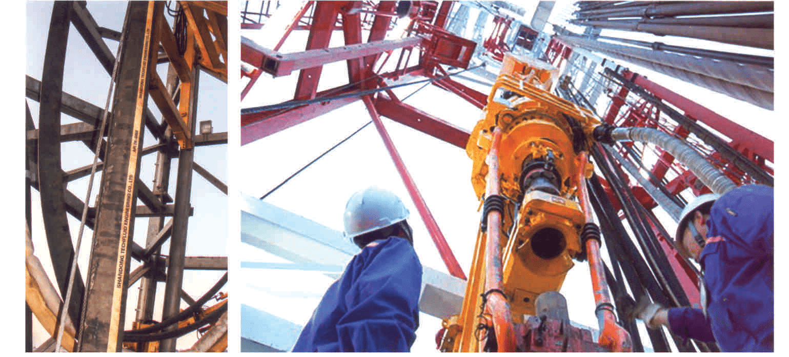
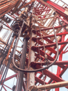
Application
Cement hose plays a critical role in the cementing process during drilling operations. It serves as a flexible conduit between the cementing pump and the top drive, facilitating the delivery of high-pressure cement to the desired location within the wellbore.
This crucial component ensures that cement is effectively pumped downhole to create a reliable seal between the casing and the surrounding formation, thus preventing potential fluid migration and providing structural integrity to the wellbore.
The flexibility of the cement hose allows for smooth and efficient operations, enabling precise control over the placement of cement slurries in various wellbore configurations, including offshore and land drilling rigs.
Standard
API Spec 7K, ISO 6807, and GB/T 24145
industry standards that specify requirements for the design, manufacture, and testing of flexible hoses used in drilling and cementing operations in the oil and gas industry. These standards ensure that hoses meet stringent quality and performance criteria to withstand the demanding conditions encountered during drilling activities, thereby enhancing safety and reliability in offshore and land drilling operations. Adherence to these standards is crucial for ensuring the integrity and effectiveness of hoses in conveying drilling fluids, cement slurries, and other essential materials in oil and gas exploration and production processes.
API Monogram No.
7K-0458
The API Monogram No. 7K-0458 signifies that the product, in this case, likely a hose, has been manufactured in accordance with the requirements outlined in API Spec 7K. This monogram indicates that the product has undergone rigorous quality control measures, adhering to industry standards to ensure its reliability and performance in demanding drilling environments. Having the API Monogram No. 7K-0458 instills confidence in customers, as it demonstrates compliance with established criteria for design, manufacturing, and testing, reinforcing the product’s suitability for use in offshore and land drilling operations.
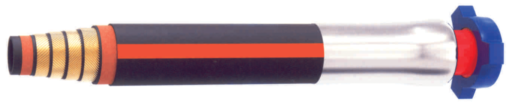
Hose Structure
Tube: Featuring a Nitrile rubber-based liner, this hose’s sealing layer offers exceptional resistance to oil, acids, alkalis, high temperatures, and aging. This ensures durability and reliability even in harsh environments.
Breaker Layer and External Protection Layers: Reinforced with high-tension textile fabric, these layers provide additional strength and protection, enhancing the hose’s ability to withstand external forces and abrasion.
Major Reinforcement: The hose is fortified with high-strength steel cables, providing superior resistance to pressure. This reinforcement ensures the hose maintains its integrity and performance even under high-pressure conditions encountered in drilling operations.
Cover: The cover, composed of Neoprene-based rubber, offers a range of protective properties tailored for marine environments. It provides anti-flaming capabilities, wear resistance, oil resistance, ozone resistance, aging resistance, and UV resistance, ensuring the longevity and reliability of the hose in offshore drilling settings.
Fire Proof Grade
Fire-Rated Hose supplied as per request with extra fire proof out layers meet fire proof grade SR6B, which is 704℃×30min
Embedded electric heat trace cable is available as request for low temperature operating
Different option of external protection layer are available as request or by our recommendation according to individual operation condition, for example stainless steel armor outer wrap, embedded stainless steel wire in cover, or polyethylene spiral guard,
Working temperature range: class II , -25℃ to +100℃
Flexibility specification level: FSL2
Maximum continuous length: 70m
Length tolerance: Length up to 4m, with tolerance ± 64 mm; Length longer than 6.4M with tolerance ± 1%
Internal Dia- meter (inch) (mm) | Outer Dia- meter (inch) (mm) | Working Pressur (bar) (psi) | Test Pressure (bar) (psi) | Flame Shield | S Safety Coeffi- cien | FSL | MBR (Storage) (m) | MBR (Operation) (m) | WT Weight (kg/m) | L Length Max (m) | ||||
| 2 | 51 | 3.43 | 87 | 345 | 5,000 | 690 | 10,000 | No | 2.5 | FSL2 | 0.8 | 0.9 | 10.2 | 70 |
| 2.5 | 64 | 4.02 | 102 | 345 | 5,000 | 690 | 10,000 | No | 2.5 | FSL2 | 0.8 | 0.9 | 13.6 | 70 |
| 3 | 76 | 4.49 | 114 | 345 | 5,000 | 690 | 10,000 | No | 2.5 | FSL2 | 1.1 | 1.2 | 15.4 | 70 |
| 3.5 | 89 | 5.16 | 131 | 345 | 5,000 | 690 | 10,000 | No | 2.5 | FSL2 | 1.2 | 1.3 | 20 | 70 |
| 4 | 102 | 5.71 | 145 | 345 | 5,000 | 690 | 1 0,000 | No | 2.5 | FSL2 | 1.2 | 1.4 | 22.4 | 70 |
| 5 | 127 | 7.52 | 191 | 345 | 5,000 | 690 | 10,000 | No | 2.5 – | FSL2 | 1.4 | 1.5 | 47.8 | 70 |
| 6 | 152 | 8.5 | 216 | 345 | 5,000 | 690 | 1 0,000 | No | 2.5 | FSL2 | 1.6 | 1.8 | 58 | 70 |
| 2 | 51 | 3.9 | 99 | 517 | 7,500 | 1,034 | 15,000 | No | 2.5 | FSL2 | 1.1 | 1.2 | 18.2 | 70 |
| 2.5 | 64 | 4.74 | 120.5 | 517 | 7,500 | 1,034 | 1 5,000 | No | 2.5 | FSL2 | 1.1 | 1.2 | 26.4 | 70 |
| 3 | 76 | 5.28 | 134 | 517 | 7,500 | 1,034 | 15,000 | No | 2.5 | FSL2 | 1.2 | 1.3 | 30.2 | 70 |
| 3.5 | 89 | 5.79 | 147 | 517 | 7,500 | 1,034 | 1 5,000 | No | 2.5 | FSL2 | 1.2 | 1.3 | 36.4 | 70 |
| 4 | 102 | 6.3 | 160 | 517 | 7,500 | 1,034 | 15,000 | No | 2.5 | FSL2 | 1.3 | 1.4 | 40.4 | 70 |
| 5 | 127 | 7.32 | 186 | 517 | 7,500 | 1,034 | 15,000 | No | 2.5 | ‘ FSL2 | 1.4 | 1.5 | 48.2 | 70 |
| 2 | 51 | 3.9 | 99 | 690 | 10,000 | 1,034 | 1 5,000 | No | 2.25 | FSLO | 1.1 | 1.2 | 18.2 | 70 |
| 2.5 | 64 | 4.74 | 120.5 | 690 | 10,000 | 1,034 | 1 5,000 | No | 2.25 | FSLO | 1.2 | 1.3 | 26.4 | 70 |
| 3 | 76 | 5.28 | 134 | 690 | 10,000 | 1,034 | 15,000 | No | 2.25 | FSLO | 1.3 | 1.4 | 30.2 | 70 |
| 3.5 | 89 | 5.79 | 147 | 690 | 1 0,000 | 1,034 | 1 5,000 | No | 2.25 | FSLO | 1.3 | 1.4 | 36.4 | 70 |
| 4 | 102 | 6.3 | 160 | 690 | 10,000 | 1,034 | 15,000 | No | 2.25 | FSLO | 1.3 | 1.4 | 40.4 | 70 |