
Brochure
Download our document to see specific data of the service and how we work.
Let’s Start Work
Together
Please feel free to contact us. We will get back to you with 1-2 business days. Or just call us now.
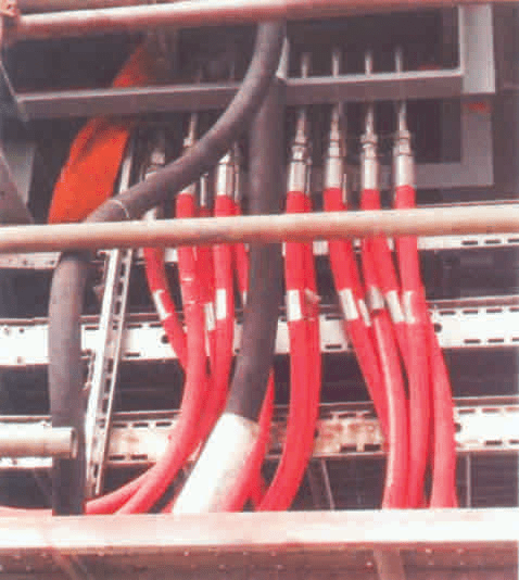
Application
The BOP (Blowout Preventer) hydraulic hose is a critical component used for the hydraulic control of Blowout Preventers in oil and gas drilling operations. Its primary function is to transmit hydraulic pressure to the BOP stack, enabling the operation of the BOP control system. This hydraulic system is essential for controlling the wellbore pressure and preventing blowouts during drilling operations.
The BOP hydraulic hose is designed to withstand high-pressure conditions, with an operating pressure of 5000 PSI (pounds per square inch). This ensures reliable performance and safety during critical operations.
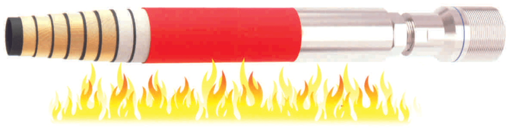
Moreover, the BOP hydraulic hose is engineered to withstand extreme temperatures and exposure to flames. It can be directly exposed to flames for more than 5 minutes at temperatures up to 704℃ (1300°F), ensuring the control system can remain operational even during emergencies such as blowouts or well control incidents.
Hose Structure
The BOP (Blowout Preventer) hydraulic hose is engineered with a robust structure to withstand the demanding conditions of oil and gas drilling operations. Its components include:
Tube: The inner tube is crafted from black smooth nitrile rubber, providing excellent oil resistance, seawater resistance, high-temperature resistance, and resistance to acids and alkalis. This ensures the hose can withstand the corrosive effects of petroleum products, seawater, and harsh chemicals.
Reinforcement: The hose features reinforcement provided by high-tension steel wire. This reinforcement enhances the hose’s strength and durability, allowing it to withstand high-pressure hydraulic applications encountered during BOP operations.
Fire Shield Layer: The hose includes a fire shield layer made of glass fiber cloth. This layer acts as a protective barrier, providing additional resistance to fire and heat, ensuring the integrity of the hose even when exposed to flames or high temperatures.
Cover: The outer cover is made of red chloroprene rubber, offering fire resistance, wear resistance, ozone and ageing resistance, and oil resistance. This protective cover shields the hose from external elements such as abrasion, ozone, UV radiation, and oil, ensuring long-term durability and reliable performance in various operating conditions, including those with potential fire hazards.
Temperature Range
The BOP hydraulic hose is designed to operate effectively within a wide temperature range, ensuring its suitability for various environmental conditions encountered in oil and gas drilling operations. Its temperature specifications typically range from −40∘C−40∘C to +121∘C+121∘C.
This broad temperature tolerance allows the hose to maintain its functionality and performance across a range of temperatures, from extremely cold conditions to elevated temperatures encountered in drilling environments. Whether exposed to freezing temperatures or high-temperature drilling operations, the hose remains capable of reliably transmitting hydraulic pressure to control Blowout Preventers.
Internal Dia- meter (inch) (mm) | Outer Dia- meter (inch) (mm) | Working Pressure (bar) (psi) | Burst Pressure (bar) (psi) | S Safety Coefficien | MBR (mm) | WT Weight (kg/m) | L LengthMax (m) | Negative Pressure (Kpa) | ||||
3/4 | 19 | 1.22 | 31 | 10 | 150 | 40 | 600 | 4 | 85 | 0.7 | 100 | -90 |
1 | 25 | 1.46 | 37 | 10 | 150 | 40 | 600 | 4 | 100 | 1.1 | 100 | -90 |
1-1/4 | 32 | 1.77 | 47 | 10 | 150 | 40 | 600 | 4 | 130 | 1.3 | 100 | -90 |
1-1/2 | 38 | 2.00 | 53 | 10 | 150 | 40 | 600 | 4 | 150 | 1.5 | 100 | -90 |
2 | 51 | 2.60 | 66 | 10 | 150 | 40 | 600 | 4 | 300 | 2.1 | 100 | -90 |
2-1/2 | 64 | 3.11 | 79 | 10 | 150 | 40 | 600 | 4 | 420 | 2.2 | 100 | -90 |
3 | 76 | 3.62 | 92 | 10 | 150 | 40 | 600 | 4 | 400 | 3.1 | 100 | -90 |
4 | 102 | 4.84 | 123 | 10 | 150 | 40 | 600 | 4 | 550 | 5.2 | 100 | -90 |
5 | 127 | 5.90 | 150 | 10 | 150 | 40 | 600 | 4 | 650 | 7.3 | 100 | -90 |
6 | 152 | 6.90 | 175 | 10 | 150 | 40 | 600 | 4 | 800 | 8.9 | 100 | -90 |
8 | 203 | 9.25 | 238 | 10 | 150 | 40 | 600 | 4 | 1,100 | 18 | 100 | -90 |